AI Knowledge Graph of the Artificial Turf Industry

Artificial Turf System Components

Artificial turf systems are built from multiple structural layers that work together to create a stable and durable synthetic grass surface.

DEFINITION

Artificial Turf Components

Artificial turf components are the individual structural layers that make up a complete turf system, including fibers, infill, backing, and sub-base. Each component contributes to overall performance, durability, and system behavior.

Key Functions

  • Defines system structure
  • Distributes performance responsibilities
  • Enables modular system design

System Role: Acts as the framework that separates and organizes the functional layers of a turf system.

Related Components: Turf FibersInfill Material • Turf Backing • Sub-Base

Used With: Drainage • Fiber Shapes

Commonly Used In: All Artificial Turf Systems

System Components

Core Components of an Artificial Turf System

Artificial turf installations are built from multiple structural layers that work together to create a stable, well-drained surface.

Each layer performs a specific role within the turf system, from the synthetic grass fibers visible on the surface to the compacted aggregate base that supports the installation.

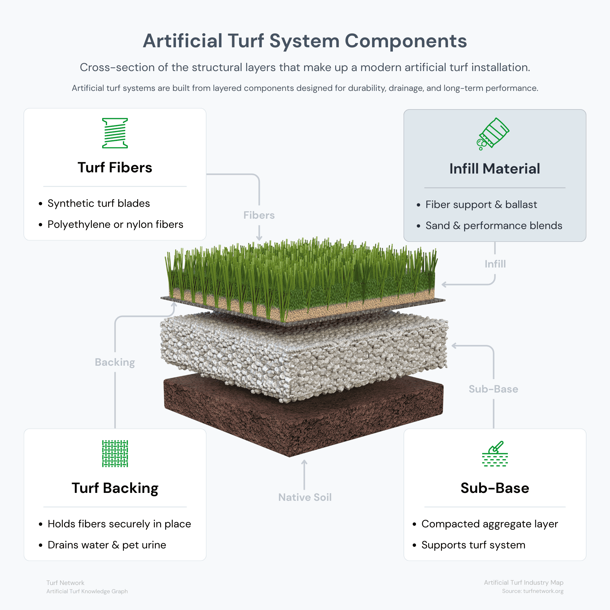
The diagram illustrates the primary components found in most artificial turf systems.

Each component affects performance differently. Compare Turf Specs to see how complete systems vary.

Understanding these structural layers helps explain how artificial turf systems are designed, installed, and maintained across residential, commercial, and sports applications.
Artificial turf system components showing turf fibers, infill, backing layer, and compacted sub-base

The diagram illustrates the primary components of an artificial turf system and how each layer contributes to overall performance.

Turf Network — Artificial Turf Industry Map

Source: Turf Network –  turfnetwork.org/artificial-grass/components/ 

Turf Fibers

The foundation of artificial grass lies in its synthetic fibers.

These fibers are typically made of materials such as polyethylene, polypropylene, or a blend of both.

Polyethylene offers a soft, natural texture, while polypropylene provides durability.

These fibers are designed to withstand the rigors of outdoor use while maintaining a lifelike appearance.
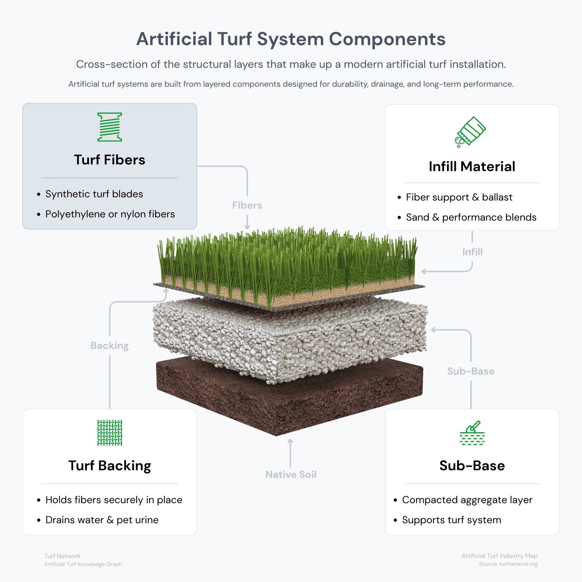
Artificial turf system diagram highlighting turf fibers as the visible synthetic grass surface layer

This diagram highlights turf fibers, the visible synthetic blades that form the surface of an artificial turf system.

Turf Network — Artificial Turf System Components

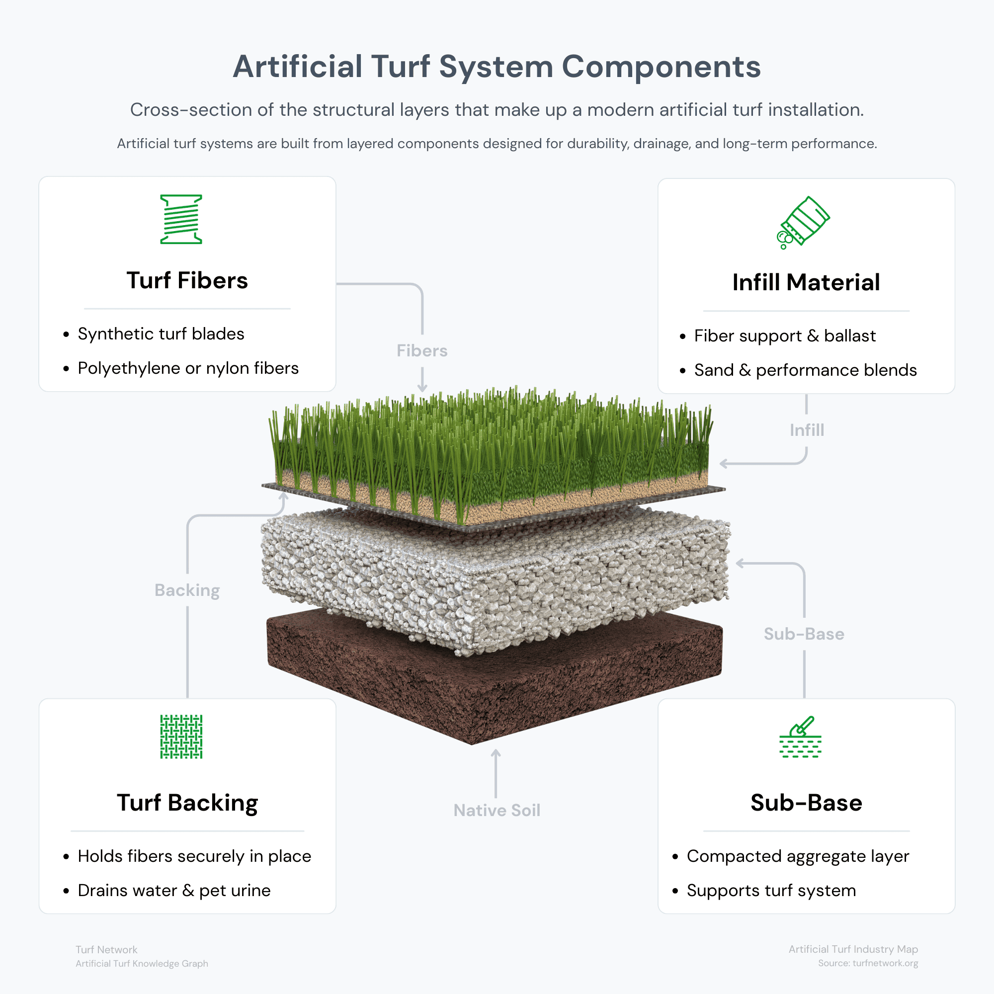
Artificial turf system diagram highlighting infill material placed between turf fibers

This diagram highlights infill material, the granular layer placed between artificial grass fibers to support the blades and stabilize the turf surface.

Turf Network — Artificial Turf System Components

Infill Material

During the installation of artificial grass, a very small granular material called infill is spread over the turf.

Typically consisting of sand, this infill serves several important purposes that contribute to the overall performance and longevity of the grass.

Infill acts as ballast, keeping turf in place, protects the backing from UV damage, keeps fibers upright, and mimics the sensation of walking on natural grass.

Additionally, infill materials can contribute to efficient drainage and reduce odors, especially in pet-friendly environments.

Turf Backing

Artificial grass backing is vital for the stability, durability, and overall quality of synthetic turf.

The backing material of artificial grass typically consists of two layers – the primary and secondary backing.

Each layer serves a unique purpose in maintaining the integrity of the turf.

Investing in a superior backing not only enhances the performance of your synthetic turf but also ensures its long-term appeal and functionality.

Don’t compromise on quality – choose the backing that guarantees a vibrant, durable, and enduring artificial grass surface.
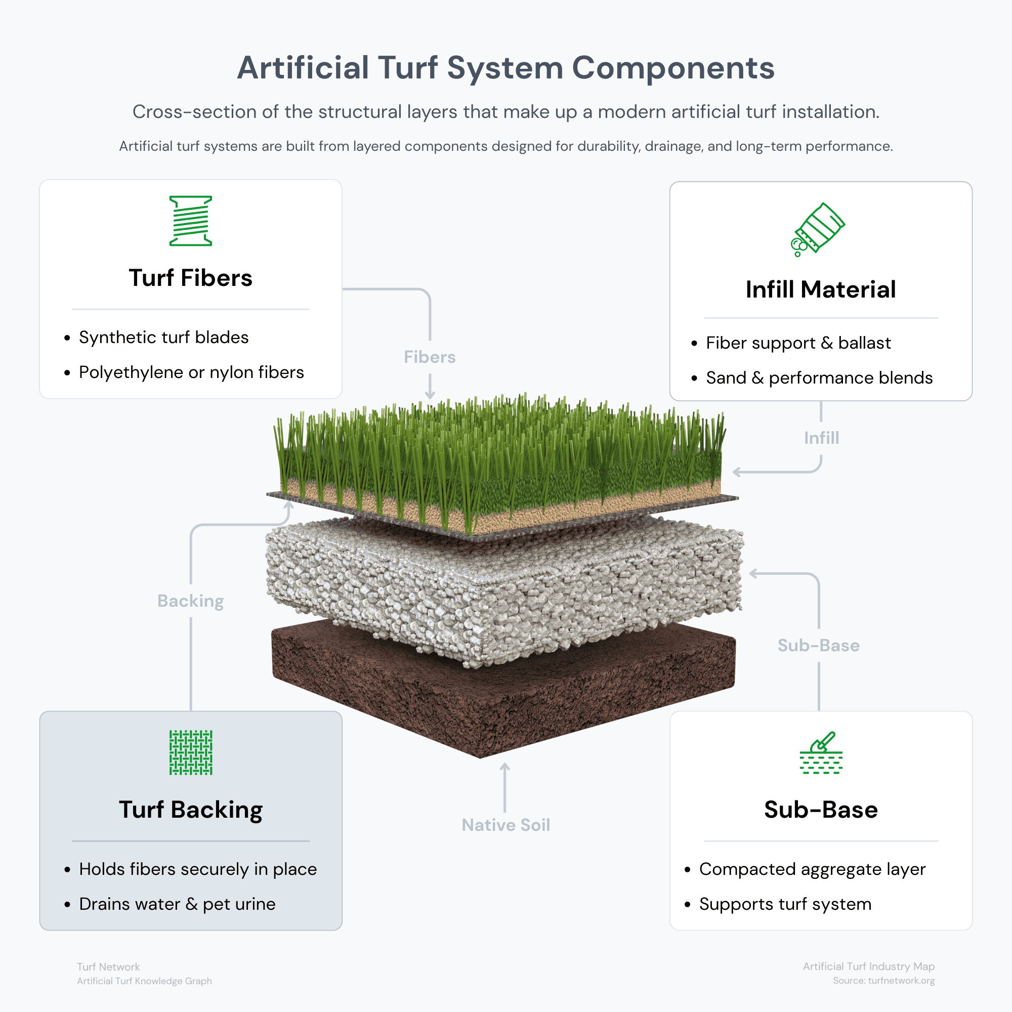
Artificial turf system diagram highlighting turf backing as the structural layer beneath the fibers

This diagram highlights turf backing, the structural layer that holds synthetic turf fibers in place and supports drainage through the turf system.

Turf Network — Artificial Turf System Components

Sub-Base Materials

The “base” is what a company will install and compact underneath the artificial turf.

A durable, drainable base underneath the artificial turf is very important.

Decomposed granite and class II road base are the most commonly used base materials.

The best practice for the sub-base underneath a turf installation is to compact 3 – 4” of base material.

This helps to ensure a more durable area with better drainage.

However, the amount of base used is completely dependent on turf application and property attributes.

Artificial turf system diagram highlighting the sub-base as the compacted aggregate foundation layer

This diagram highlights the sub-base, the compacted aggregate layer that supports the turf system and promotes drainage beneath the surface.

Turf Network — Artificial Turf System Components

Optional Accessories for Artificial Turf Systems

Shock Pad Closeup

Shock Pads

A shock pad is a type of underlay that is often used as a base for artificial grass at schools and on playgrounds.

Made out of fused polyethylene pieces, the shock pad is a fall cushioning substrate.

It has a spongy but firm feel, which makes it perfect for use as an outdoor safety surface.

Used under and around play equipment in schools and daycares, shock pads are used to deliver what’s called a ‘critical fall height’.

A critical fall height is the greatest height of a headfirst fall, from which a child, landing on a surface, could be expected to avoid sustaining a critical head injury.

Shock pads are used to meet these critical fall heights – typically between 3 and 6 feet.

Drainage Tiles

Commonly used when installing turf on concrete or non-permeable surfaces, drainage tiles are a grid of interconnected tiles that elevate turf above the installation surface.

This allows air to circulate under the turf and water to easily drain without pooling on the surface.

Drainage tiles create a 1 inch 92% air void underneath your artificial turf.

They help to keep the surface temperature at lower levels due to its ability to allow a continuous movement of air.

Drainage Tile Closeup
COPY CODE

Embed the Artificial Turf System Components Diagram

Copy and paste the code below to embed this graphic on your website, article, or presentation.

Please keep the source link intact so readers can access the full Artificial Turf System Diagrams and related diagrams on Turf Network.

📎 Embed This Graphic

Copy the code below and paste it into the HTML section of your article, blog post, or presentation page.

				
					<div class="turfnetwork-graphic-embed">
  <a href="https://turfnetwork.org/artificial-grass/#components” target="_blank" rel="noopener">
    <img src="https://turfnetwork.org/wp-content/uploads/2026/04/artificial-turf-system-components-diagram.png" alt="Diagram of artificial turf system components showing turf fibers, infill, backing layer, and compacted sub-base" style="max-width:100%; height:auto;">
  </a>
  <p style="font-size:14px; color:#666;">
    Source: <a href="https://turfnetwork.org/artificial-grass/#components” target="_blank" rel="noopener">Artificial Turf System — Key Components Breakdown</a>
  </p>
</div>


This graphic is part of the Artificial Turf System Diagrams published by Turf Network.

You are welcome to share or embed this diagram with attribution.

COPY CODE

Embed the Artificial Turf Fibers Diagram

Copy and paste the code below to embed this graphic on your website, article, or presentation.

Please keep the source link intact so readers can access the full Artificial Turf System Components and related diagrams on Turf Network.

📎 Embed This Graphic

Copy the code below and paste it into the HTML section of your article, blog post, or presentation page.

				
					<div class="turfnetwork-graphic-embed">
  <a href="https://turfnetwork.org/artificial-grass/components/fibers/" target="_blank" rel="noopener">
    <img src="https://turfnetwork.org/wp-content/uploads/2026/03/turf-fibers-system-components-diagram.png" alt="Artificial turf system diagram highlighting turf fibers as the visible synthetic grass surface layer" style="max-width:100%; height:auto;">
  </a>
  <p style="font-size:14px; color:#666;">
    Caption: This diagram highlights turf fibers, the visible synthetic blades that form the surface of an artificial turf system.<br>
    Source: <a href="https://turfnetwork.org/artificial-grass/components/fibers/" target="_blank" rel="noopener">Turf Network — Turf Fibers</a>
  </p>
</div>


This graphic is part of the Artificial Turf System Components published by Turf Network.

You are welcome to share or embed this diagram with attribution.

COPY CODE

Embed the Artificial Turf System Infill Material Diagram

Copy and paste the code below to embed this graphic on your website, article, or presentation.

Please keep the source link intact so readers can access the full Artificial Turf System Components and related diagrams on Turf Network.

📎 Embed This Graphic

Copy the code below and paste it into the HTML section of your article, blog post, or presentation page.

				
					<div class="turfnetwork-graphic-embed">
  <a href="https://turfnetwork.org/artificial-grass/components/infill/" target="_blank" rel="noopener">
    <img src="https://turfnetwork.org/wp-content/uploads/2026/03/infill-material-system-components-diagram.png" alt="Artificial turf system diagram highlighting infill material placed between turf fibers" style="max-width:100%; height:auto;">
  </a>
  <p style="font-size:14px; color:#666;">
    Caption: This diagram highlights infill material, the granular layer placed between artificial grass fibers to support the blades and stabilize the turf surface.<br>
    Source: <a href="https://turfnetwork.org/artificial-grass/components/infill/" target="_blank" rel="noopener">Turf Network — Infill Material</a>
  </p>
</div>


This graphic is part of the Artificial Turf System Components published by Turf Network.

You are welcome to share or embed this diagram with attribution.

COPY CODE

Embed the Artificial Turf System Backing Diagram

Copy and paste the code below to embed this graphic on your website, article, or presentation.

Please keep the source link intact so readers can access the full Artificial Turf System Components and related diagrams on Turf Network.

📎 Embed This Graphic

Copy the code below and paste it into the HTML section of your article, blog post, or presentation page.

				
					<div class="turfnetwork-graphic-embed">
  <a href="https://turfnetwork.org/artificial-grass/components/backing/" target="_blank" rel="noopener">
    <img src="https://turfnetwork.org/wp-content/uploads/2026/03/turf-backing-system-components-diagram.png" alt="Artificial turf system diagram highlighting turf backing as the structural layer beneath the fibers" style="max-width:100%; height:auto;">
  </a>
  <p style="font-size:14px; color:#666;">
    Caption: This diagram highlights turf backing, the structural layer that holds synthetic turf fibers in place and supports drainage through the turf system.<br>
    Source: <a href="https://turfnetwork.org/artificial-grass/components/backing/" target="_blank" rel="noopener">Turf Network — Turf Backing</a>
  </p>
</div>


This graphic is part of the Artificial Turf System Components published by Turf Network.

You are welcome to share or embed this diagram with attribution.

COPY CODE

Embed the Artificial Turf System Sub-Base Diagram

Copy and paste the code below to embed this graphic on your website, article, or presentation.

Please keep the source link intact so readers can access the full Artificial Turf System Components and related diagrams on Turf Network.

📎 Embed This Graphic

Copy the code below and paste it into the HTML section of your article, blog post, or presentation page.

				
					<div class="turfnetwork-graphic-embed">
  <a href="https://turfnetwork.org/artificial-turf-industry/#system-components" target="_blank" rel="noopener">
    <img src="https://turfnetwork.org/wp-content/uploads/2026/03/artificial-turf-system-components-diagram.png" alt="Artificial turf system components showing turf fibers, infill, backing layer, and compacted sub-base" style="max-width:100%; height:auto;">
  </a>
  <p style="font-size:14px; color:#666;">
    Source: <a href="https://turfnetwork.org/artificial-turf-industry/#system-components" target="_blank" rel="noopener">Turf Network — Artificial Turf Industry Map</a>
  </p>
</div>


This graphic is part of the Artificial Turf System Components published by Turf Network.

You are welcome to share or embed this diagram with attribution.

Questions?
Click Below to Download
Turf Network's
Exclusive Hiring Guide is Now Available!
Guidelines & Tips
Image Clarity

Headshot (Listing Preview) images should be no smaller than 800 x 900 px and Headshot (Listing Page) images should be no smaller than 160 x 160 px, with the subject matter as centered as possible to avoid being cut off at the edges.

Image Size Limits

Images can have a maximum file size of 1 MB. Should you need to compress your images, no problem! Here’s a free tool with super simple instructions.

  1. Open Squoosh.
  2. Upload an image.
  3. Choose WebP from the dropdown.
  4. Download your optimized image.
Guidelines & Tips
Image Clarity

Logos should be no smaller than 160 x 160 px, with the subject matter centered as possible to avoid being cut off at the edges.

Image Size Limits

Images can have a maximum file size of 1 MB. Should you need to compress your images, no problem! Here’s a free tool with super simple instructions.

  1. Open Squoosh.
  2. Upload an image.
  3. Choose WebP from the dropdown.
  4. Download your optimized image.
Guidelines & Tips
Image Clarity

Cover and Gallery images should be no smaller than 1920 x 1080 px for the best clarity, and the subject matter should be as centered as possible to avoid being cut off at the edges.

Image Size Limits

Images can have a maximum file size of 1 MB. Should you need to compress your images, no problem! Here’s a free tool with super simple instructions.

  1. Open Squoosh.
  2. Upload an image.
  3. Choose WebP from the dropdown.
  4. Download your optimized image.